
Component-Modeled Filter Bank
TVGCMF
Twelve very good filters. Twice. In a row.
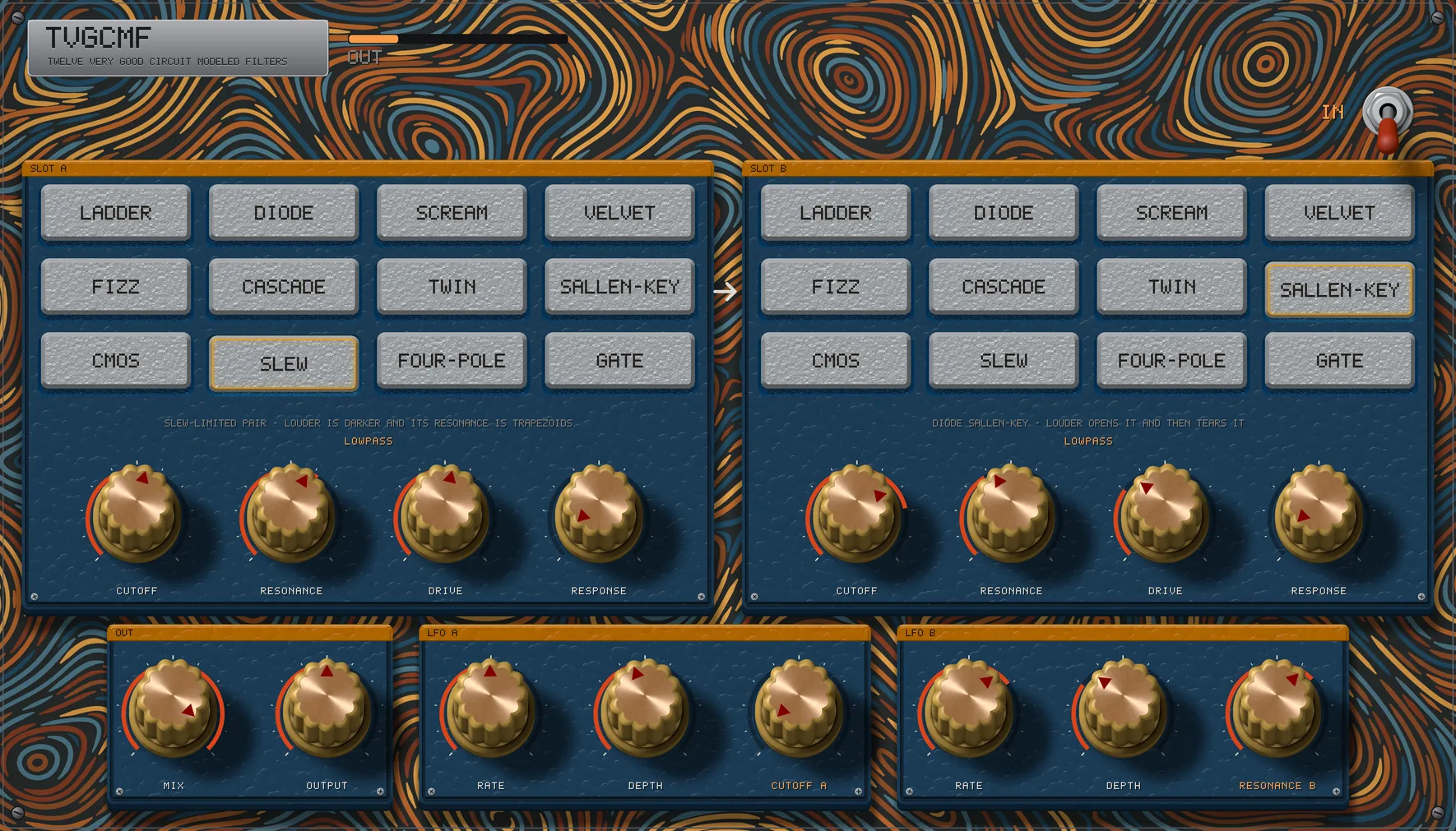
Twelve Very Good Circuit Modeled Filters, and the panel says so in small print under the logo. All twelve are on the surface at once - no menu, no drop-down, twelve buttons you hit without aiming - and behind the first slot is a second slot of the same twelve, in series.
Every one of them is built from its parts - transistor pairs, diodes, OTAs, a photocell - and solved every sample, with every feedback loop solved inside the sample it happens in rather than a sample late.
Run a diode ladder into a vactrol gate. Run a transistor ladder into itself. Switch the second slot out when you do not want it. Two LFOs sit along the bottom and can be pointed at any dial on the panel.
VST3 · Windows 64-bit·No activationmacOS is in development.
Demos
One take, 12 ways
The same thirty-two seconds, played once and then run through the plugin 12 times. The dry one is straight out of Realgar Red's oscillators, with nothing else on it - no filter, no envelope, no effect - so what you are hearing these circuits do, they are doing to raw oscillators. Every take is the whole of it and lines up with the dry one sample for sample, so you can switch between them and hear the filter rather than the edit. Nothing is level-matched here on purpose: a filter that takes the bottom out is quieter, and hiding that would be hiding the filter.
Realgar Red's oscillators, and nothing else
cutoff, very slowly · 7.2 dB of swing
cutoff - the squelch · 15.6 dB of swing
resonance · 9.7 dB of swing
drive - louder is darker · 11.4 dB of swing
cutoff, slowly - the vactrol answering late · 3.2 dB of swing
cutoff · 3.0 dB of swing
cutoff - highpass and lowpass together · 4.5 dB of swing
both cutoffs, drifting apart · 5.4 dB of swing
cutoff A and resonance B · 26.3 dB of swing
both cutoffs, locked together · 3.4 dB of swing
mix - the whole effect breathing · 5.6 dB of swing
both cutoffs, fast · 8.3 dB of swing
The swing is measured rather than described: the take's envelope divided by the dry one's, so the music cancels and what is left is how far the filter's own gain travelled. five of the 12 run a pair of circuits in series; the rest are one slot. The bench refuses a take that moves less than 3 dB, because a demonstration of a moving filter whose filter does not move is a filtered take with a misleading name.
The short answer
Twelve filters, on the surface, twice
Most filter plugins give you one circuit and a menu of modes, or a menu of circuits you have to go and find. TVGCMF puts all twelve circuits on the panel at once, as buttons, and then gives you a second slot of the same twelve in series behind the first. Comparing them is pressing a button, not opening a list, and stacking two of them is pressing one more. Every circuit is staged to arrive at the same loudness as its neighbours, so the one that sounds best is not just the one that got louder.
And every one is solved, not approximated. Each circuit is built from its parts: the ladders' transistor pairs at their thermal voltage, diodes by the diode equation, OTAs by their curve, the gate's photocell by its carriers. Wherever a circuit feeds back, the loop is solved inside the sample it happens in, the parts included, rather than fed back a sample late to make the arithmetic easy - which is what moves a resonance off its pitch. You can see it in the numbers.
twelve circuits
Each one is a different idea, not a different setting
These are twelve topologies rather than twelve presets of one filter: different parts, different faults, different manners when you drive them. The panel calls each one what it is built from, and the line under the buttons says what it does to a signal.
- LADDERA transistor ladder. It compresses, and it loses its bottom.
- DIODEA diode ladder whose rungs load each other. It squelches.
- SCREAMA discrete Sallen-Key with its diodes in the signal path. It clips, and its resonance leaves the bass alone.
- VELVETA two-pole state-variable on bare OTAs that will not self-oscillate. Ring it hard and the resonance compresses from inside.
- FIZZA discrete state-variable: bare OTAs and a diode limiter, which is the fizz.
- CASCADEAn OTA cascade whose cells see only how far each stage lags. Louder is darker, and at the top it screams.
- TWINA resonant highpass into a resonant lowpass.
- SALLEN-KEYThe diode version: louder opens it, and then tears it.
- CMOSLogic inverters asked to be op-amps. It blunts and fizzes.
- SLEWA slew-limited pair. Louder is darker, and the resonance is trapezoids.
- FOUR-POLEAn op-amp integrator cascade. The clean one, and it keeps its bottom.
- GATEA vactrol low-pass gate. The cutoff is a lamp; the photocell answers fast and lets go ever more slowly.
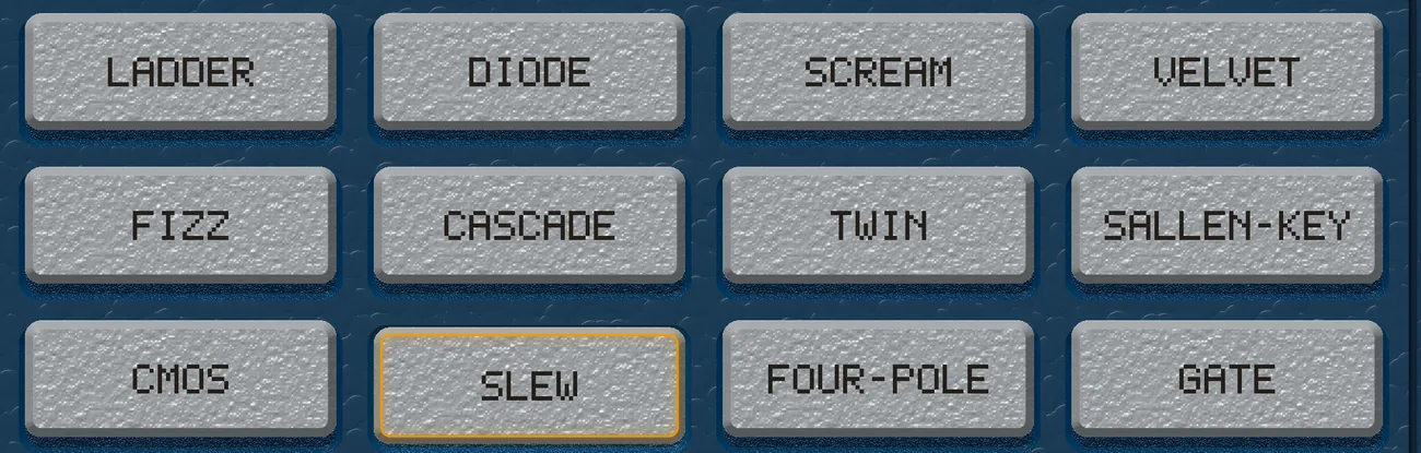
Measured, at matched settings: 200 Hz stands over 9 kHz by 7.0 dB on GATE, which is the flattest of them by design, and by 54.2 dB on DIODE. All twelve are stable at full drive and full resonance.
Why a selector is hard
You are hearing the circuit, not the gain
On a synthesizer you choose a filter once and build the patch around it. Here you compare twelve of them by pressing a button - and whichever arrives loudest wins that comparison, whatever it actually sounds like. So every circuit is staged to land at the same loudness at the same settings, and the bench holds it there.
Changing circuit does not click: the slot crossfades over about five milliseconds and the outgoing filter keeps running until it has faded, so the tail of what you were listening to survives the switch. The second slot is eased in and out for the same reason - dropping a filter into a signal path is a step in the output, and so is lifting it out. A slot that has been out of the path starts from rest when it comes back, so nothing is left charged from last time.
Slot B
The same twelve again, behind the first
Slot B follows slot A and can be switched out of the path entirely. It is the same twelve circuits, so the pairs are yours to make: a diode ladder into a vactrol gate, a slew-limited pair into a diode ladder, or the same circuit twice. Measured: put a 400 Hz filter behind a 6 kHz one and 9 kHz falls from -34.7 dBFS to -127.7.
Two of them, free-running
Pointed at any dial on the panel
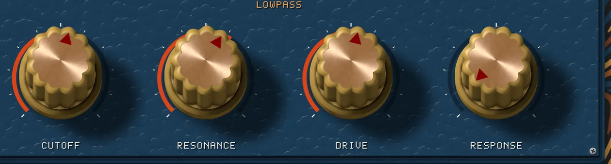
Each LFO runs in hertz and can be aimed at any of the eight per-slot dials, or at MIX. Pointed at a cutoff they move it in octaves rather than in hertz, because the dial is logarithmic and pitch is too: adding hertz to it would be inaudible at the top of the range and a lurch at the bottom.

Twice the sample rate
And the latency, told to your host
Eleven of these circuits are nonlinear in the signal itself - that is the point of each of them - and a nonlinearity at 48k folds everything above Nyquist back into the audible band as hash. (The twelfth, GATE, is a lamp: its nonlinearity is in the light, not the signal.) So every circuit runs at twice the sample rate: the signal goes up, through the filters, and back down through the same halfband the synthesizers use. That pair takes 15 samples, 0.3 ms at 48 kHz, and the plugin reports exactly that to your host, which lines everything up. MIX holds the dry signal back the same 15 samples, so the two blend instead of combing.
Twenty-four buttons, sixteen dials, one lever
The one that is in is the one that is down
The circuit in a slot is pressed down and lit: a bank of latching buttons, where the one that is in is the one that is down, and the line under each selector says what that circuit is and what its RESPONSE dial is asking of it. The two slots read left to right because that is the order the signal goes through them, with an arrow between them that says so.
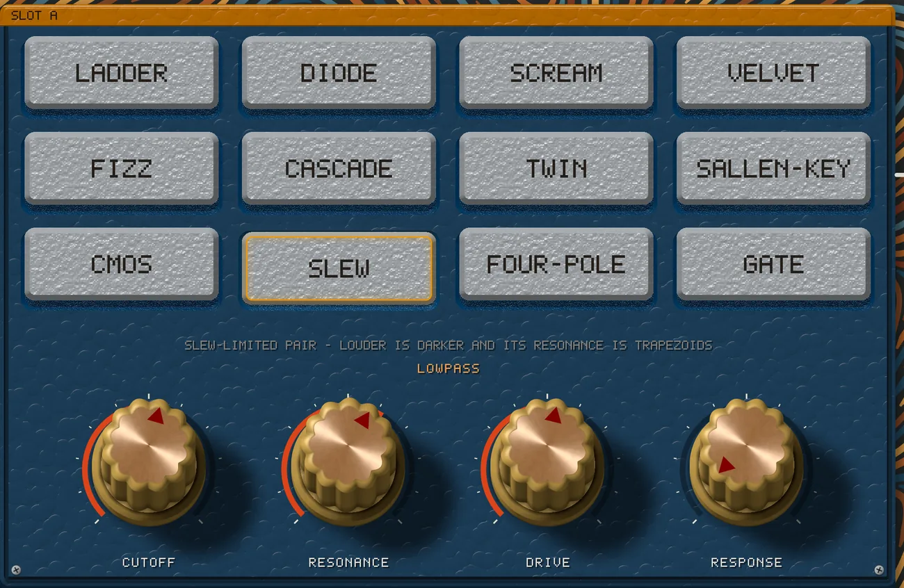
The plates are hammered blue with orange header bands and phillips screws, the caps are machined metal, and the dials are scalloped brass with an oxblood pointer and a live arc. Behind all of it is combed marbled paper, drawn by contour-packing a flow field: every stroke laid where no stroke has been, so the field stays distinct instead of turning to mush. The panel is 1456 by 832, which fits a laptop.
The sheet
What is in the box
An effect, not an instrument: audio in, audio out, no notes and nothing to play. Nineteen parameters, all of them automatable, and the stepped ones print their names rather than a number.
Powered by Phonon
The filters the flagship uses
These are not impressions of the circuits inside our instruments. They are the twelve in Realgar Red's filter bays, compiled from the same source, solved the same way, put on a panel where you can reach all twelve at once and stack two of them. The rest of what we build draws on the same library: Phonon is the engine underneath.
VST3 · Windows 64-bit·No activationmacOS is in development.
At a glance
TVGCMF specifications
| Format | VST3 effect · Windows 64-bit |
|---|---|
| In development | macOS |
| Circuits | 12, in two slots in series · the second switchable, off by default |
| Per slot | CIRCUIT, CUTOFF (20 Hz to 18 kHz), RESONANCE, DRIVE, RESPONSE |
| Global | MIX and OUTPUT (±24 dB) |
| The LFOs | 2 · 0.02 to 20 Hz · aimed at any per-slot dial, or MIX |
| Level spread | 3.7 dB across the twelve at matched settings |
| How much they filter | 200 Hz stands from 7.0 dB (GATE) to 54.2 dB (DIODE) over 9 kHz |
| Changing circuit | A crossfade · worst seam 0.12× the signal's own step |
| The solve | Every feedback loop inside the sample, the parts included · by Newton iteration where they are nonlinear, exactly where they are not |
| Oversampling | 2× · 15 samples of latency (0.3 ms at 48 kHz), reported to the host |
| Parameters | 19, all automatable · stepped ones print their names |
| Panel | 1456 by 832 |
| Activation | None. No license server, no phone-home |